01 · DEFINE
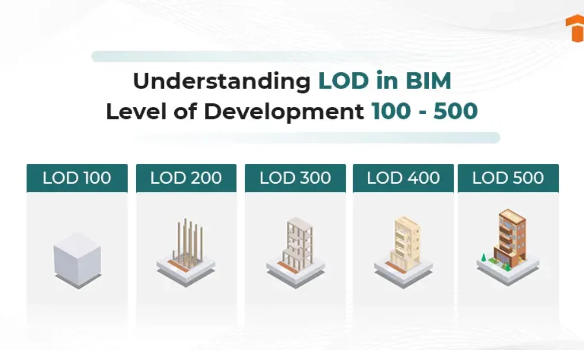
LOD, use and tolerances
Agree target use, LOD/LOI, required disciplines, modeling tolerances, naming, coordinate system and exchange formats.

We support Scan-to-BIM and BIM production from client-provided point clouds, scans, drawings and project requirements. The model scope is organized around intended use, Level of Development, tolerance and required information—not geometry alone.
 POINT CLOUD
ENGINEERING DATA
GIS INTELLIGENCE
Scan-to-BIM deliverables require a clear specification for coordinate systems, registration quality, modeling rules, tolerances and information requirements. Defining these at the start reduces ambiguity during production and review.
Agree target use, LOD/LOI, required disciplines, modeling tolerances, naming, coordinate system and exchange formats.
Develop the agreed building or asset elements from the supplied scan data, using the selected BIM workflow and model standards.
Review fit to the available reference data, element completeness, information fields and model organization before delivery.
Scan-to-BIM transforms client-provided point clouds, scans and references into structured building information models. The right model scope depends on the purpose, required categories, level of development and tolerance agreed with the client.
Agree the elements to model, required parameters, coordinate setup, exclusions, modelling tolerance and use case before production.
Build the required Revit/BIM elements from the available scan evidence. Complex geometry, occluded areas and incomplete scan coverage may need assumptions or client decisions.
Check model-to-point-cloud fit, levels, coordinates, categories, family behavior, naming and model usability for the agreed downstream workflow.
LOD is not a universal accuracy promise. The level of detail, information content and geometric tolerance should be documented separately for each project.
Illustrative outputs from related geospatial workflows. Final deliverables are agreed to the project specification.
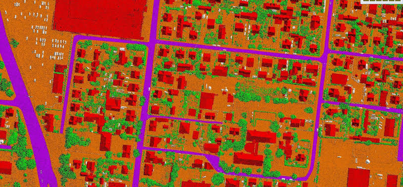
Model accuracy depends on source scan quality, registration, visibility and the agreed tolerance. The target LOD and model uses should be defined before production.